Mighty Mule Gate Lock Wiring Diagram

The gate must not exceed 8 ft.
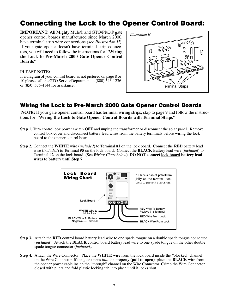
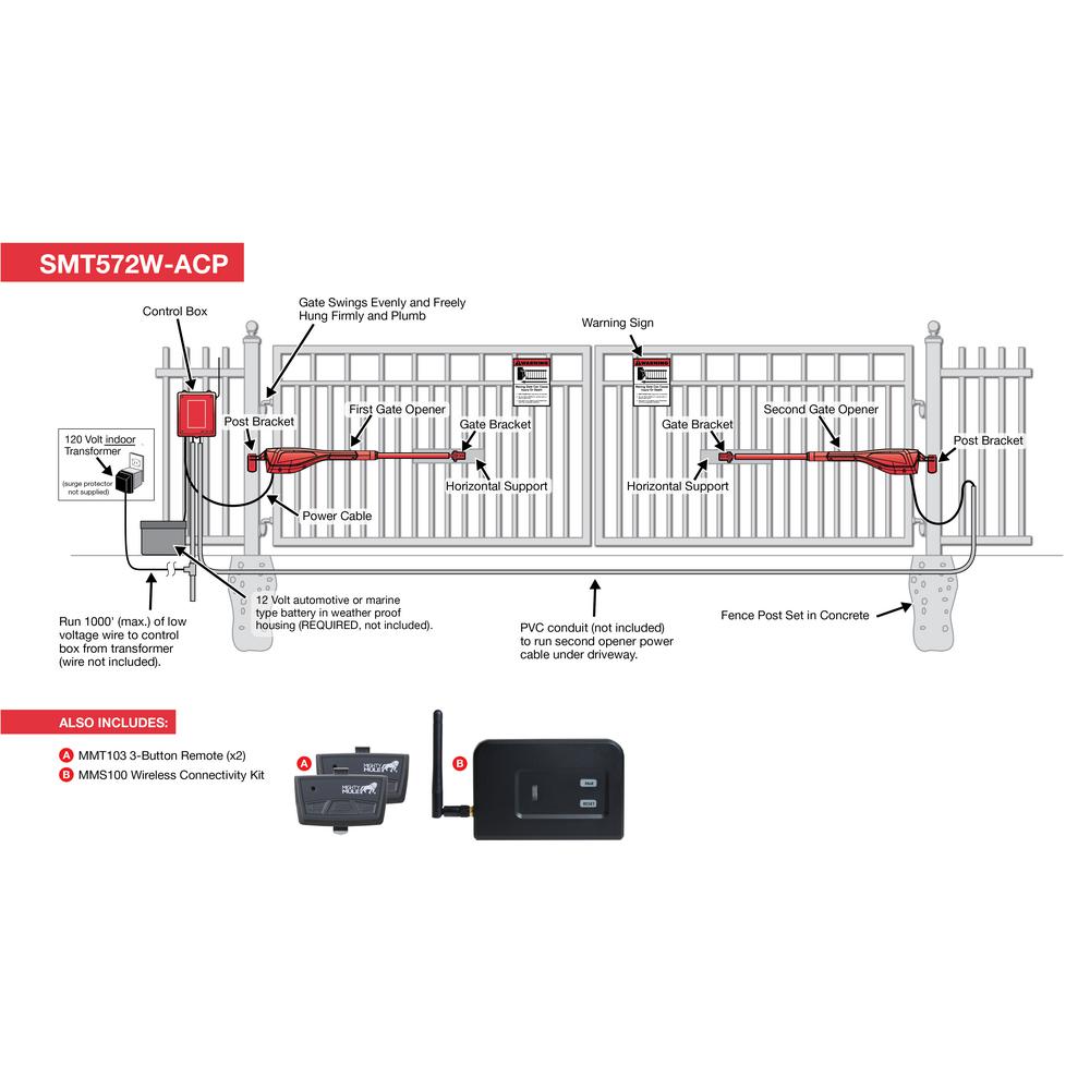
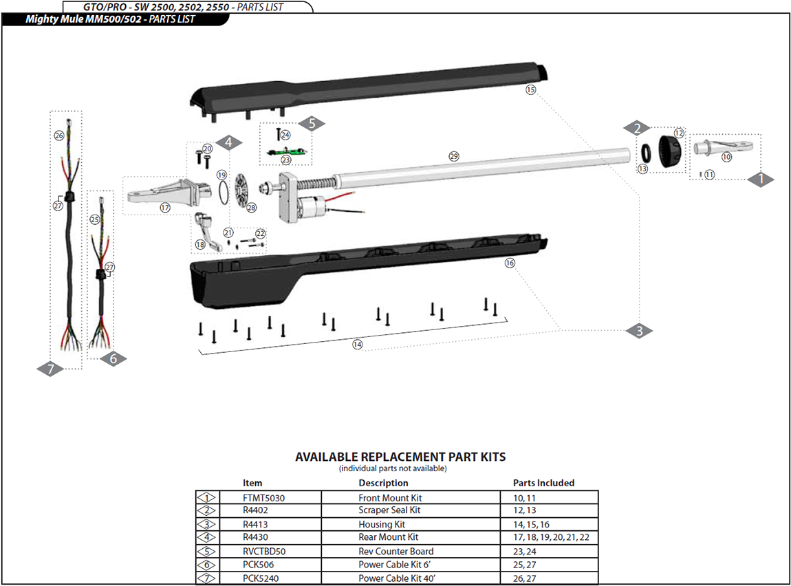
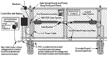
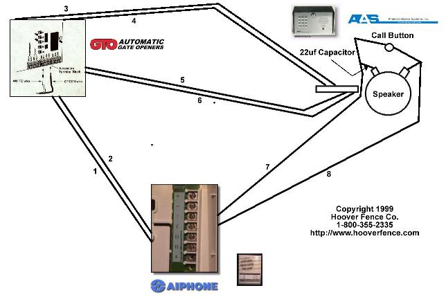
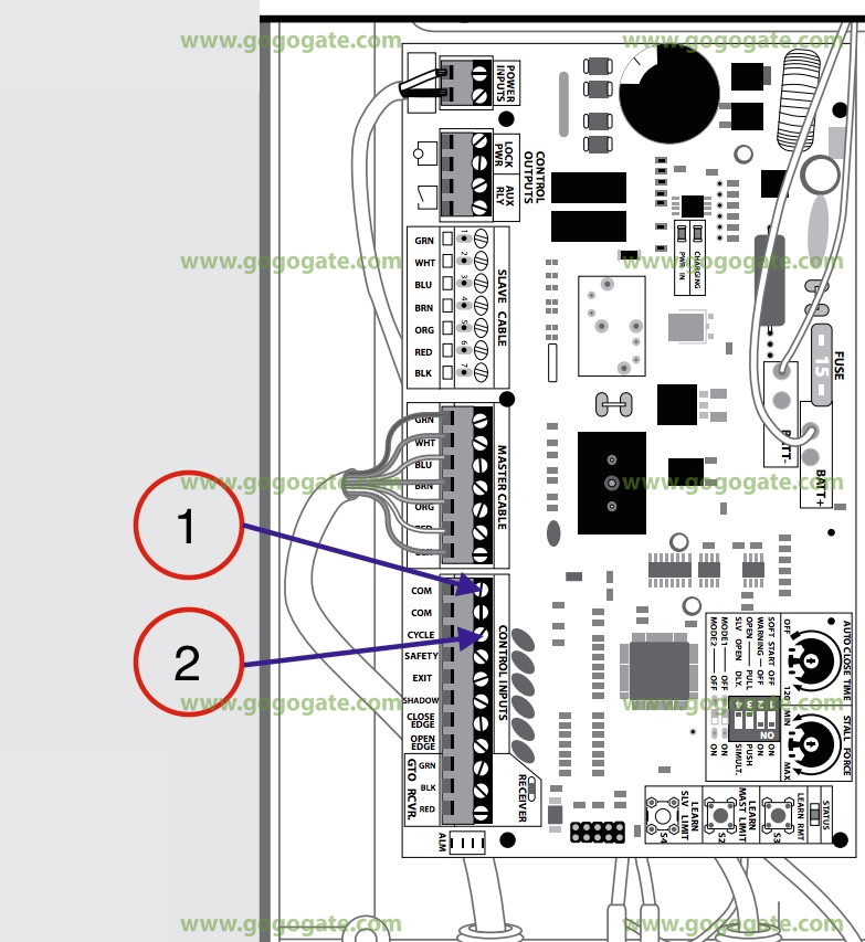
Mighty mule gate lock wiring diagram. Open push to open diagram on page 9. The mighty mule gate opener accommodates extra transmitters digital keypads solar panels and other. It reveals the components of the circuit as simplified shapes and the power and signal connections in between the tools. Page 35 the gate opening sensor is designed for residential and agricultural applications and is compatible with mighty mule automatic gate openers.
The diagrams below will show how most dual gto pro and mighty mule gate sequencing is. It unlocks and locks automatically as the gate is activated to open and clos. 1 855 644 4891. Mighty mule accessories.
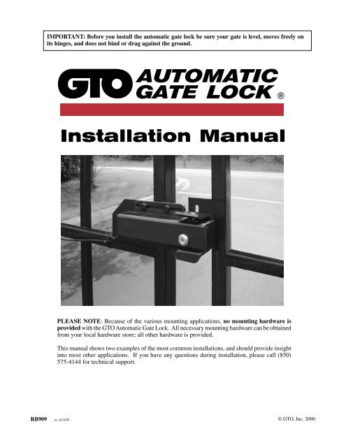
Use the retail search tool to find genuine mighty mule products online or in store. Or 550 lbs or exceed 16 ft. With the sequencing set correctly follow the steps and diagrams below to mount the lock to the gates. The sensor is an electromagnetic sensor which offers hands free operation of the mighty mule gate opener with a 12 ft.
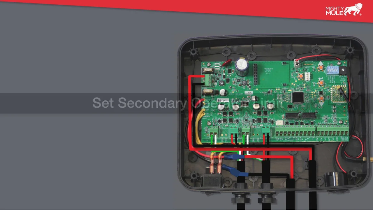
Mighty mule and gto technical support for your mighty mule or gto automatic gate opener and access controls. In this video we demonstrate how to wire a solenoid gate lock to the liftmaster control board. M f 8am 7 00pm est. Assortment of mighty mule gate opener wiring diagram.
Gate openers driveway gates garage door openers. Wiring the lock to pre march 2000 gate opener control boards red wire to battery positive terminal. Substitute a pin lock fm133 for the clevis pin on. Radius of detection of vehicles in motion.


